20/01/2013
- Yet more on the roll bar
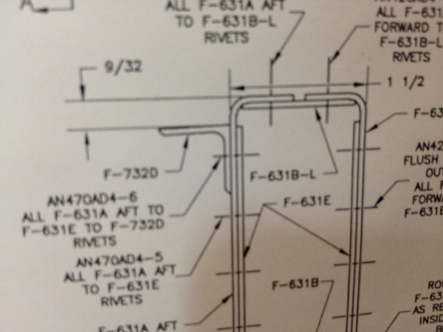
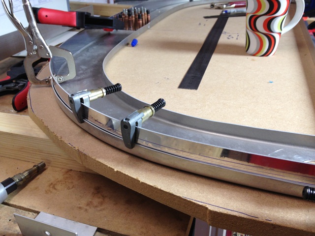
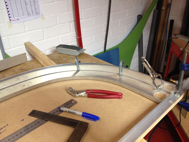
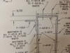
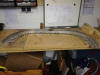
Starting with the joining plate for the rear part of the roll bar,
be careful to check the drawings as F-732D sits on the back of the
roll bar an is riveted through the same holes as F-631E.
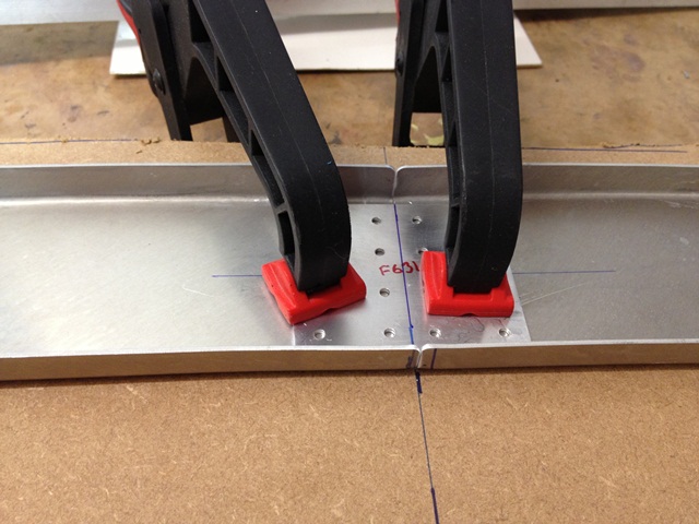
F-631E is positioned 9/32 from the top of the roll bar.

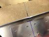
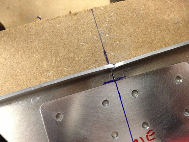
Once measured and clamped down the F-631E was
drilled to the rear of F631A, and into the board to lock
everything in place.
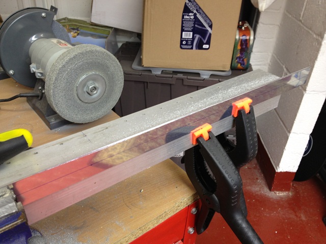
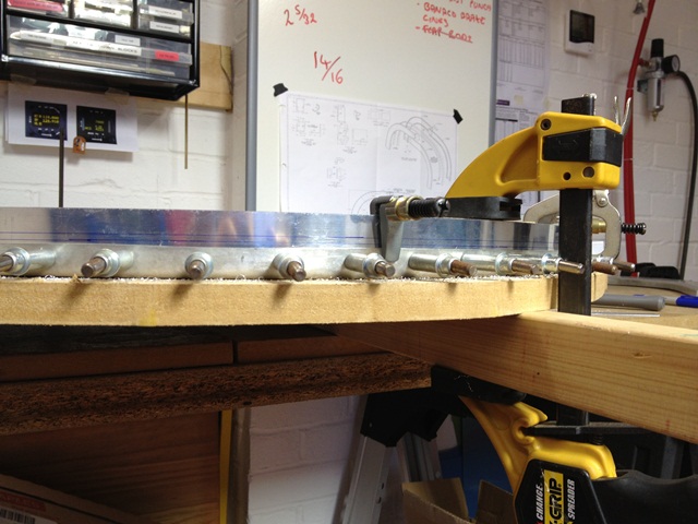
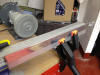
F-631B joining straps as a bit of a fiddle to get
right. Lots of filling to chamfer the edge so the
straps sit into the radius of the roll bar. If the filling
is accurate then the strap will sit vertical when clamped and sit
snugly against the flange with no gap. I found the strips
needed to be bevelled on the top and bottom (or front and back
from the plane perspective). When I clamped it down to the
channel, the top of the strip should be 1 3/8" from the particle
board.


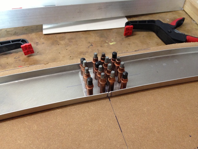
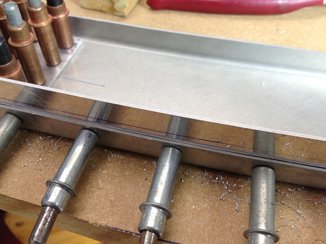
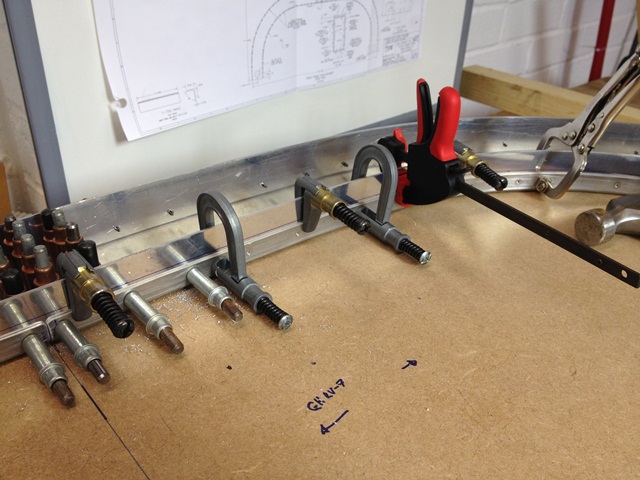
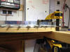
I cant remember who came up with this but to mark
out the rivet holes first mark up some masking tape and then apply
the tape to the roll bar. Mark with a hole punch and remove
the tape. Hey presto and then drill the holes. I have
gone #40 to begin with, I will get everything fitted then enlarge
them.

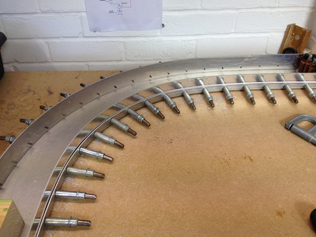
Repeat for the inner rivet holes, as per the call
outs in the plans.

So far so good
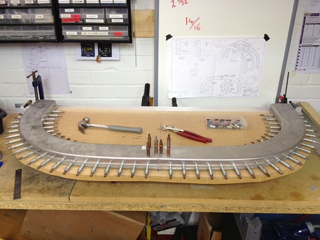
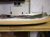
Thought I would have a trial fit of the next part
:-) Was not that happy so stripped it all down and filed
some parts again. When I pit it back together there was a
much better fit.

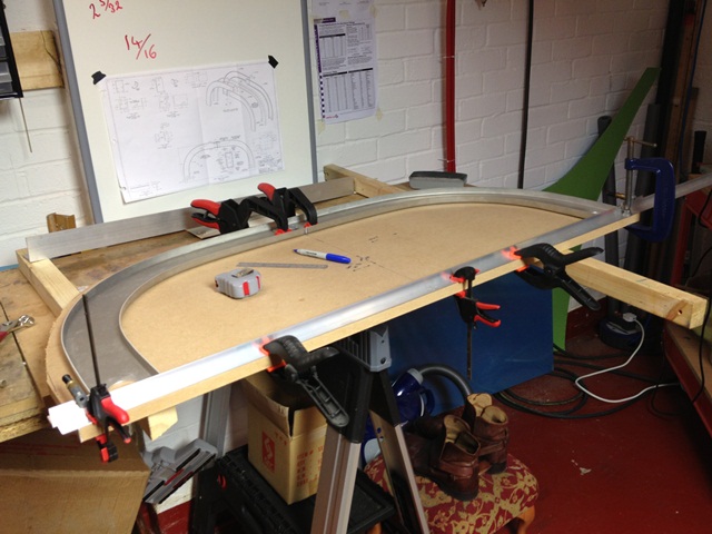
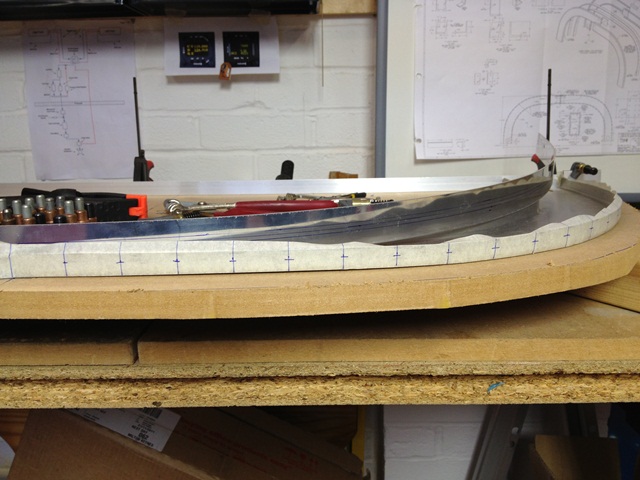
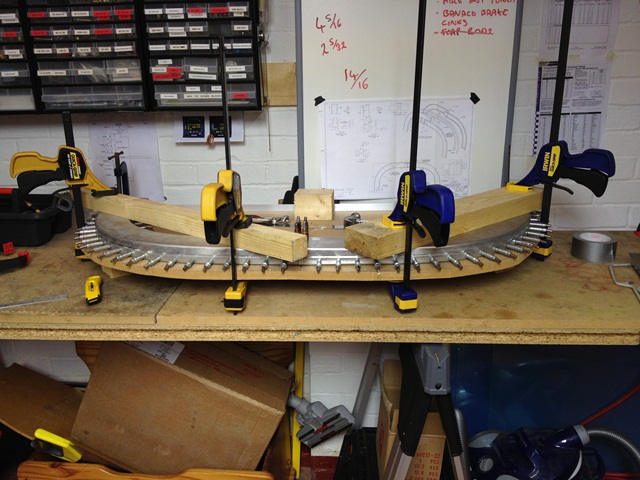
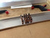
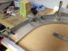
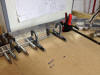
So I just had sufficient
enough time to clamp down the front part of the roll bar. I
have used space blocks inside the roll bar so I can clamp the unit
down to the required width of 1.5".
The blocks are 1 3/8" in height made out of 2x4
timber so that the whole frame will have a width of 1.5" when
clamped down.